


BWSENSING provides a reliable inertial navigation and map correction solution for autonomous sweepers, inspection robots, and other low-speed intelligent equipments.
Shared:


Navigation Solution for Low-Speed Unmanned Intelligent Equipment
BWSENSING provides a reliable inertial navigation and map correction solution for autonomous sweepers, inspection robots, robot dogs, unmanned patrol platforms and other low-speed intelligent equipment operating in GNSS-denied or GNSS-challenged environments.
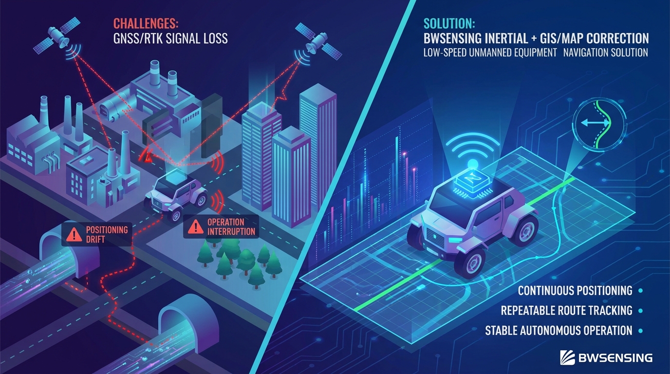
Reliable Positioning When Satellite Signals Are Unavailable
Low-speed unmanned intelligent equipment is now widely used in industrial parks, underground parking lots, large factories, campuses, logistics areas and utility tunnels. These applications require continuous positioning, repeatable route tracking and stable autonomous operation.
However, conventional RTK/GNSS positioning is easily affected by buildings, steel structures, underground spaces, tree coverage and electromagnetic interference. Once satellite signals are blocked or the RTK fixed solution is lost, unmanned equipment may suffer from positioning drift, route deviation, incomplete task coverage or operation interruption.
To solve this problem, BWSENSING combines high-performance inertial navigation with GIS/map correction technology. The vehicle can continue to operate without RTK, while the real-time trajectory is periodically corrected back to the pre-surveyed reference map.

Key Challenges in Low-Speed Unmanned Operation
In real industrial scenarios, customers need a positioning system that remains stable even when GNSS, lighting or environmental conditions are not ideal.
RTK Instability in Complex Environments
Underground parking lots, large workshops, pipe galleries and areas surrounded by buildings often cannot provide stable RTK fixed solutions.
Accumulated Drift Over Long Routes
Pure inertial navigation can drift over time. Without correction, the positioning error may increase with distance and affect route tracking accuracy.
Dependence on Weather and Lighting
Vision or LiDAR-based solutions may be affected by rain, snow, dust, darkness, glare or repetitive indoor scenes. Customers need more robust navigation redundancy.
Inertial Navigation + GIS / Map Correction
The solution uses inertial navigation as the core positioning unit and combines it with BMR3000, GIS data and map correction algorithms. When RTK/GNSS is unavailable, the platform can still continue navigation along the pre-surveyed route.
Continuous operation without RTK: Maintains navigation capability in GNSS-denied environments.
Map-constrained correction: Prevents positioning error from accumulating continuously.
Strong environmental adaptability: Less affected by weather, light or day-night changes.
Flexible platform integration: Suitable for sweepers, robot dogs, inspection robots and unmanned vehicles.
Reliable route repeatability: Supports repetitive cleaning, patrol and inspection tasks.

How BWSENSING Solves Industry Pain Points
BWSENSING focuses on high-reliability positioning and navigation technologies for intelligent unmanned equipment, helping customers expand operation from open outdoor spaces to indoor, underground and satellite-denied environments.
| Capability | Customer Pain Point Solved | Customer Value |
|---|---|---|
| GI320 Inertial Navigation | RTK/GNSS signal interruption or unstable fixed solution | Provides continuous motion estimation and reduces the risk of sudden positioning failure. |
| Map Correction Technology | Accumulated drift during long-distance low-speed operation | Uses a reference map to correct the real-time trajectory and keep positioning error bounded. |
| BMR3000 + Multi-Source Fusion | Single positioning source is unreliable in complex environments | Improves navigation robustness through integrated sensing and correction. |
| All-Weather Operation | Vision or external sensing affected by light, rain, snow or dust | Supports stable operation day and night, indoors and outdoors, in different weather conditions. |
| Flexible Integration | Different unmanned platforms require adaptable navigation modules | Applicable to sweepers, robot dogs, inspection robots, patrol vehicles and other low-speed platforms. |
Inspection Robot Test in Hangzhou Industrial Park
BWSENSING conducted field tests on an Inspection Robot in Hangzhou. Under the condition of no RTK satellite signal, the vehicle relied on inertial navigation and map correction technology to complete a full 188-meter route.

April 15 Test Result
During the April 15 test, the red actual trajectory was periodically corrected back to the yellow reference map. The maximum deviations at selected points were approximately 0.81 m, 1.19 m and 1.29 m.
The positioning error remained within 1.29 m and did not continue to increase with time or distance, proving that the map correction technology effectively constrained the inertial navigation drift.
April 16 Second Verification Test
On April 16, a second verification test was conducted. At the starting point, the RTK state was no longer a fixed solution during antenna removal, resulting in an initial positioning drift of about 2.79 m.
After the vehicle moved a short distance, the trajectory was corrected back to the yellow reference map, showing that the map correction function was fully effective. The measured deviations included approximately 1.27 m at point 1 and 0.9 m at point 2.


What the Two Tests Proved
Improved Calibration Data and Better Route Convergence
In the later optimized test on April 28, after calibration data optimization, the straight-line deviation was controlled within approximately 0.57 m.
The main remaining deviations occurred at turning sections. At the first turning point, the error reached about 2.56 m due to the long antenna removal process at the start, which caused vehicle body position and heading drift. At the second turning point, the deviation was about 1.37 m.
After full-path calibration, the final endpoint deviation was reduced to approximately 0.1 m, showing a significant optimization effect.

Expanding Autonomous Operation to More Complex Sites
The GI320-based inertial navigation and map correction solution is suitable for applications where satellite positioning is unstable, unavailable or not reliable enough as the only navigation source.
Autonomous Cleaning Robots
Supports route tracking and area coverage in industrial parks, underground parking lots, warehouses, campuses and large indoor facilities.
Underground Utility Tunnel Inspection
Enables robot dogs or inspection robots to maintain positioning continuity in long, narrow and GNSS-denied underground pipe galleries.
Industrial Patrol and Security Robots
Provides reliable navigation for repetitive patrol tasks in factories, logistics parks, power facilities and semi-enclosed industrial environments.


From Site Mapping to Stable Autonomous Operation
Site Survey
Collect route information, reference landmarks and environmental data to build a high-confidence operation map.
Device Integration
Integrate GI320, BMR3000 and related navigation modules into the customer’s unmanned equipment platform.
Calibration & Tuning
Perform vehicle calibration, route matching and map correction parameter optimization based on actual conditions.
Field Verification
Verify route repeatability, deviation control and task stability through real-vehicle operation tests.
A Robust Navigation Foundation for Low-Speed Unmanned Equipment
The Hangzhou field tests verified that BWSENSING’s GI320 inertial navigation and map correction technology can support low-speed unmanned equipment in environments with severe satellite signal blockage and interference. On the 188-meter route, straight-line deviation was controlled within a practical range, with most straight sections reaching approximately the 0.2 m level and the maximum straight-line deviation within about 0.5 m in the summary results.
Although turning sections showed larger deviations due to steering control limitations of the Inspection Robot and manual remote-control constraints, the overall results demonstrated that the solution can effectively prevent error accumulation and correct the vehicle back to the reference route. This provides a reliable technical foundation for autonomous cleaning, inspection and patrol in underground parking lots, large factories, utility tunnels and other GNSS-denied environments.
Build Reliable Navigation for Your Unmanned Equipment
BWSENSING provides customizable inertial navigation, BMR3000 and map correction solutions for autonomous sweepers, inspection robots, robot dogs and other low-speed intelligent platforms.
Contact Us

-
STAY CONNECTED


-
8:00am-7:00 pm Service Online
WhatsApp/Tel:+86 15050 672 146
+86 17606 118 008
Commercial:sales@bwsensing.com
Customer Service:support@bwsensing.com

Copyright © 2010-2023 Wuxi BEWIS Sensing Technology LLC 苏ICP备14001101号-6 Privacy Policy Cookies

 +86 189 2129 2620
+86 176 0611 8008 sales@bwsensing.com